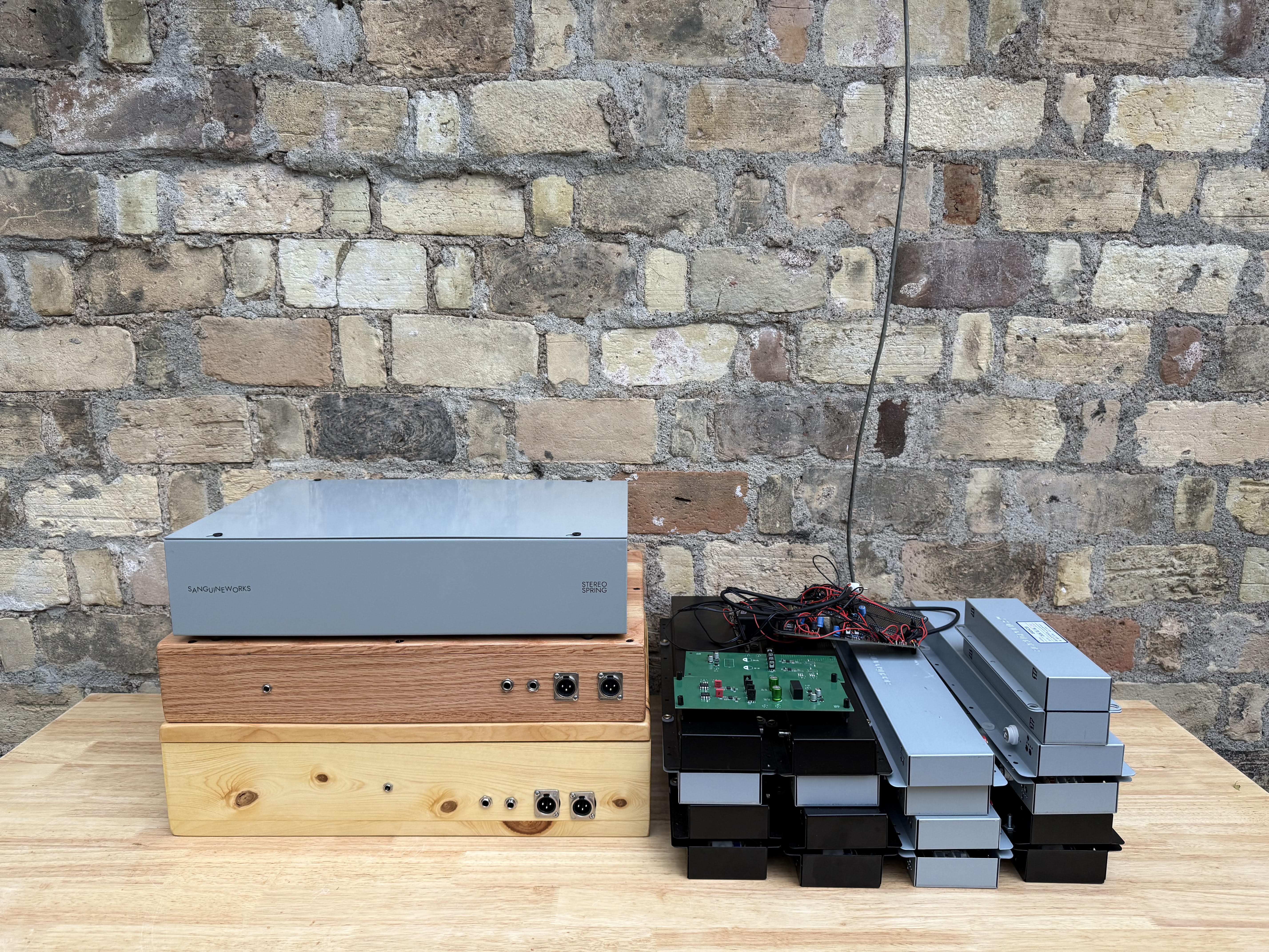
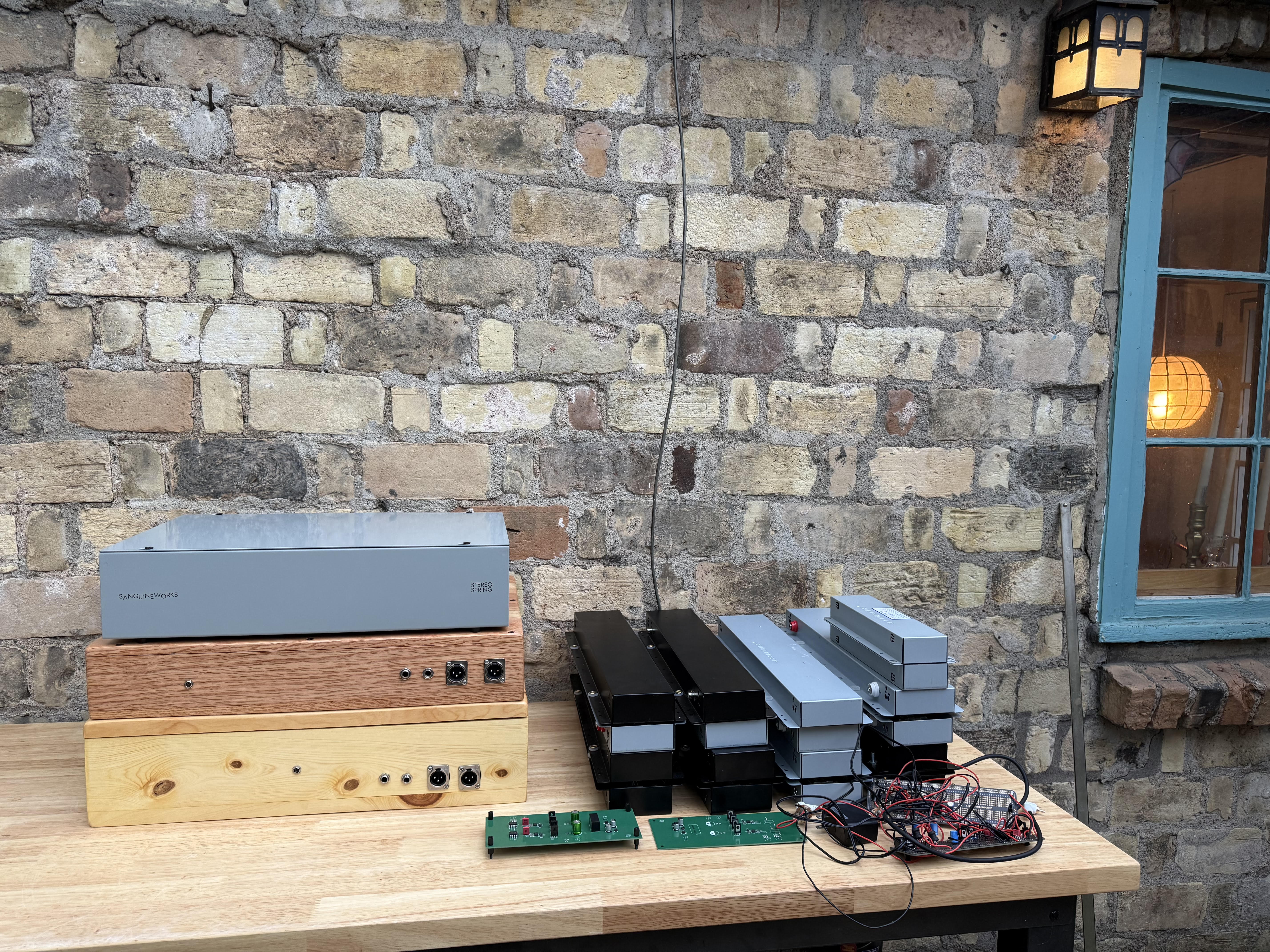
This project started in July 2026 because I couldn't find a software emulation that captured the specific sound I was after. The existing analog options I found were old units that are often noisy and hard to maintain, guitar pedals that are mostly mono, or units that cost around $1,000 with a fixed set of springs that are different for the left and right channels. I wanted to see if I could build a real stereo spring reverb at a reasonable price, with customizable spring options.
My first idea was to make it 100% passive and send the signal straight from an audio interface to the spring tanks, and use microphone preamps as the makeup gain. In testing, I found that line outputs don't have enough current to drive the springs, and it resulted in a muffled and noisy sound. After researching more, I found that an active drive stage is needed to properly drive the springs.
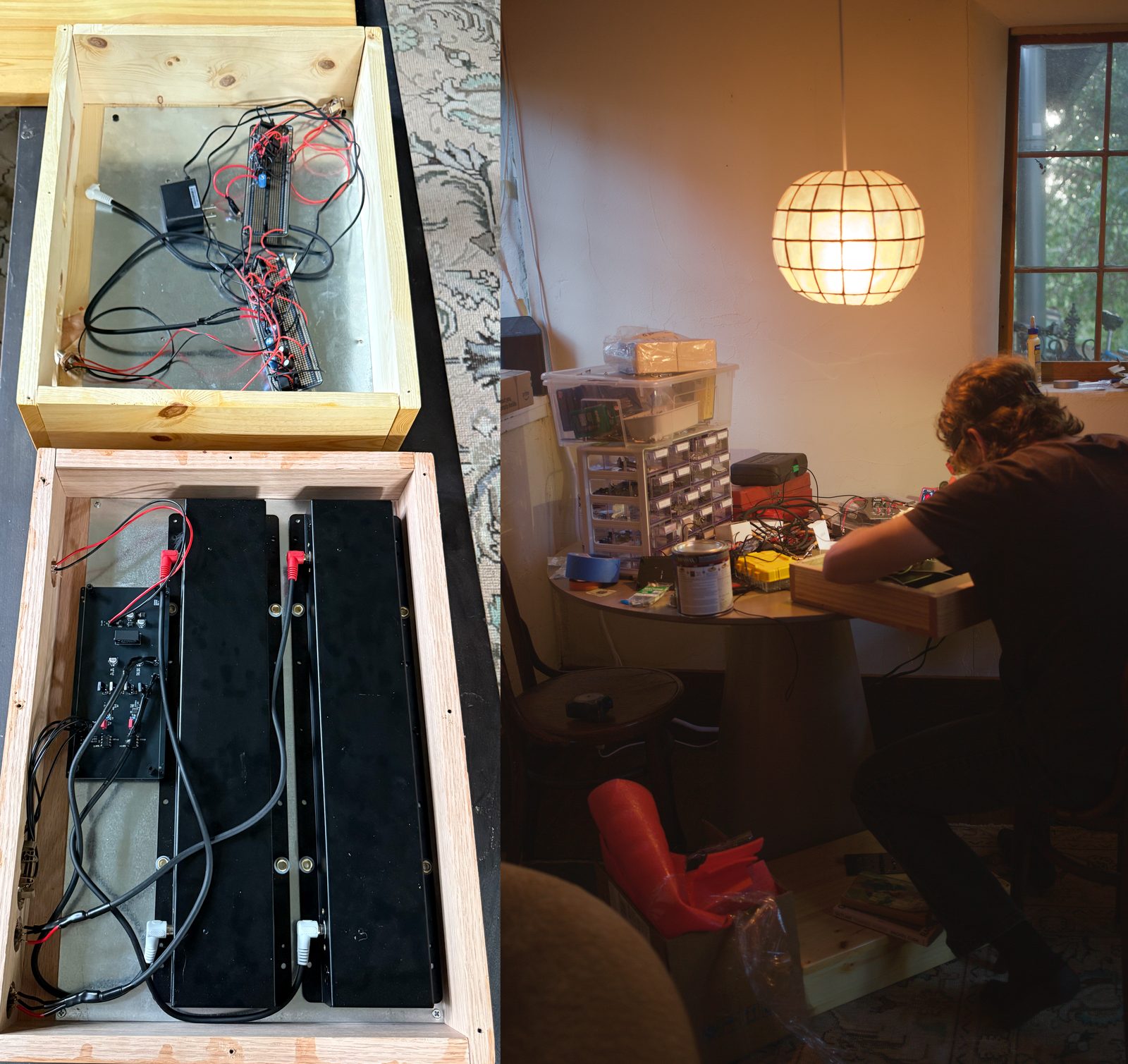
I built the first circuit board prototype by hand and spent several weeks soldering, troubleshooting, swapping components, rewiring, and deciding on EQ and gain values before I finally got a decent sounding reverb with as little radio and ground noise as possible. The other good news was microphone preamps worked well for the makeup gain, and that was a big part of the cost.
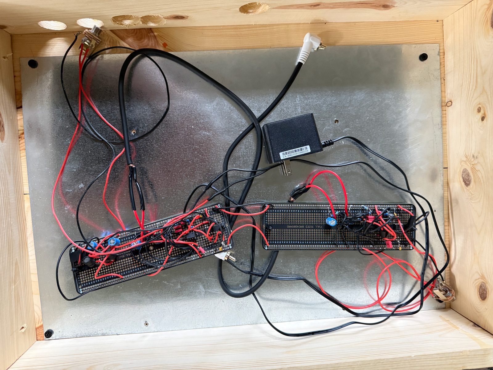
By the beginning of August, I had a working prototype. But spending days building each unit wasn't an option if I wanted to get below the $1,000 cost. So I learned how to design an SMD PCB that a factory could build with the small surface-mount parts already installed, leaving me only the larger parts to solder by hand. On my first attempt the output transistors were installed backwards (the black PCBs in the image), but luckily the second order worked great (the Rev A green PCBs).
Next was choosing the springs. My first order, when I was optimizing for passive input, turned out to be the wrong tanks. So I went back and bought a matched pair of every model I could find that worked with the new design. I recorded each one with the same source material and narrowed them down by ear to the 7 you can hear on the Samples page.
Then, in September, the company that makes the input chips announced they were discontinuing them. I tested the closest replacement, but it picked up radio where the original didn't, so I bought a reserve of the originals, enough for 500 units.
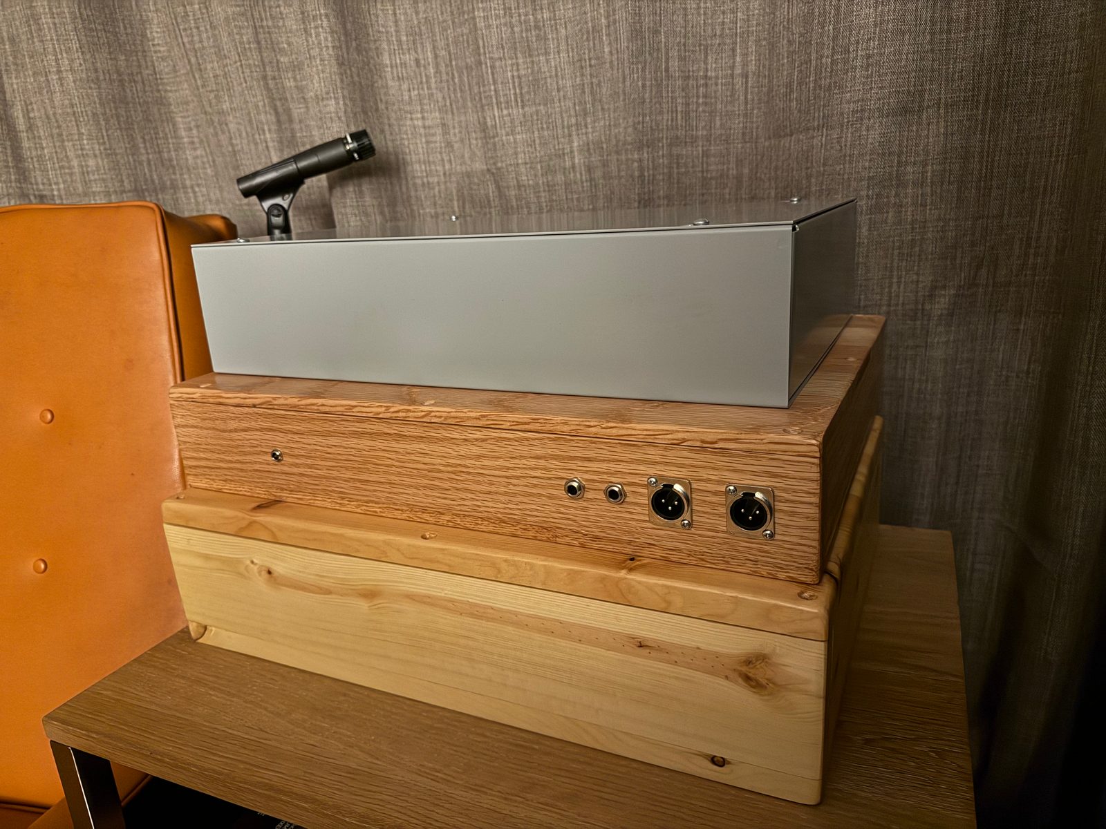
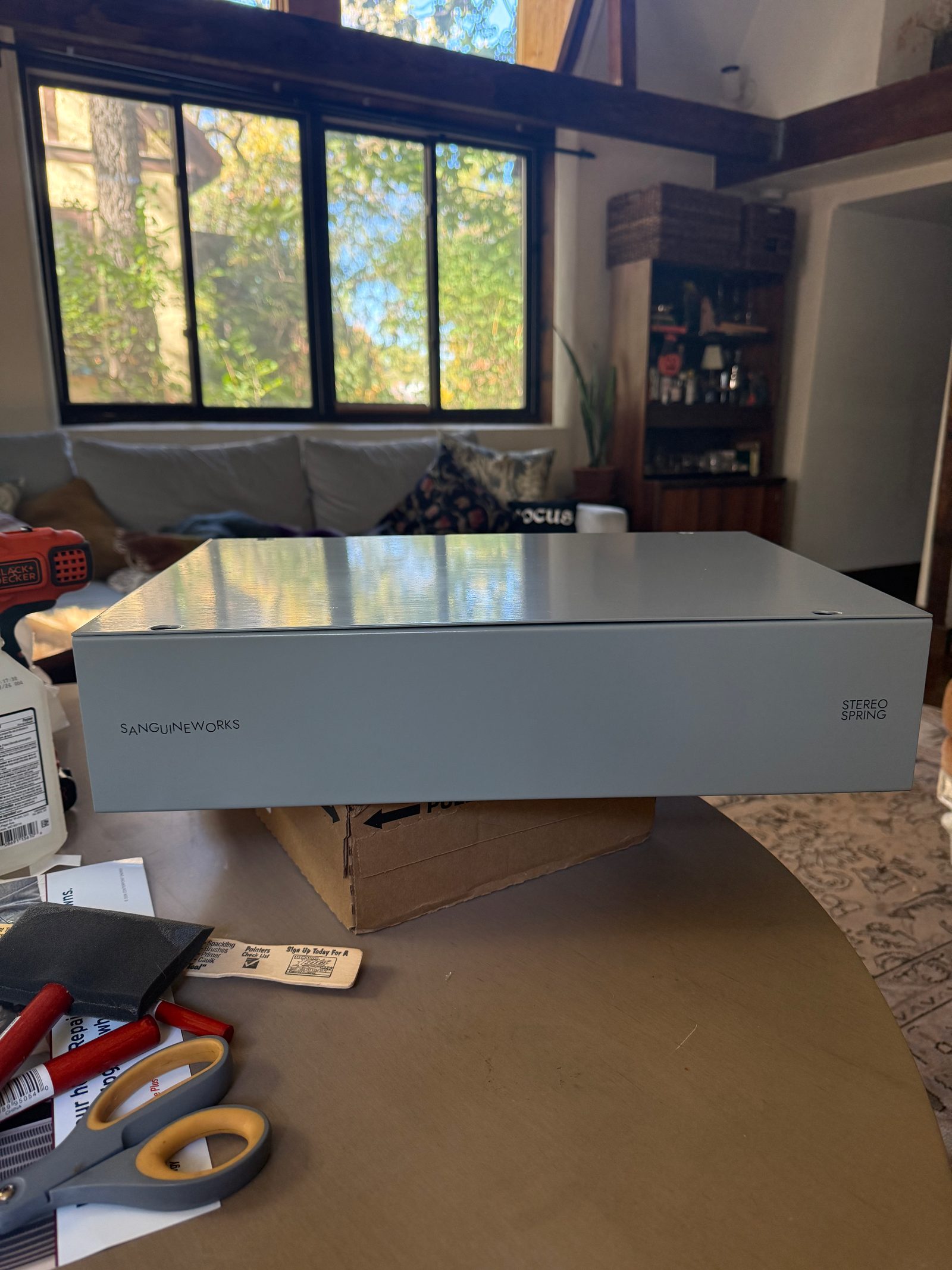
The last big decision was the enclosure. For the prototypes, I used wooden boxes, with a steel sheet underneath for shielding. Building them by hand took a lot of time, and getting clean cuts with plywood is surprisingly difficult, so I switched to a solid steel enclosure that shields the tanks on every side, and makes installing connectors consistent and durable. I am still happy to make wooden cases for anyone who prefers one, and I have proper tools now for making them studio quality. But they're solid wood and cost more.